Monday, May 27, 2013

Trebuchet: General information


History
Trebuchets were first created in China or areas around China. The trebuchet made its way to the Byzantine Empire through the nomadic Mongolian people called Avars. These weapons were used as both siege and defense weapons. After the trebuchet came to Europe, the French made certain improvements to increase range and accuracy. Apparently, trebuchets became so reliable that they were still used after the invention of cannons. The trebuchets are well known for being used in the medieval times to knock down castles and fortifications.

How It Works
A trebuchet works by using gravity and/or a heavy load and using the force to throw a projectile a long distance.  It is used like a lever, and takes advantage of the fulcrum and the pivot point to gain energy.

Physics Involved
The trebuchet uses gravity to launch the projectile. The sling uses centripetal force (a= v^2/r) to gain even more distance. The angle that the projectile is launched at will affect the outcome of the distance. When released, the potential energy of the weight changes to kinetic as it is affected by gravity, which in turn moves the arm and then the potential energy of the sling changes to kinetic as well. The velocity of the object, when graphed using x= gravity multiplied by time squared divided by 2 (x=gt^2/2) and y= velocity squared divided by gravity multiplied by 2 (y=v^2/2g), the graph will be parabolic.

Meeting 6: trials and updates

May 19,2013
Trial 1
The first trial ended up going backwards.
Trial 2
After some research, we came to the conclusion that it was the sling that was the main problem. We decided to clip the sling so that it would make a pouch for the water balloon. We also changed the location of the hooks for the sling that was most recommended which was the the closed hook be on the bottom of the the end of the wood and the open hook be on the top of the side of the wood. we also realized the sling could have been hitting the back piece of wood, so we used some cardboard to prevent that.

 As you can see, it could have went forward if it hadn't popped.

Trial 3
 At one point I figured that it might be better to have a sturdy piece of wood for the ramp instead of the flimsy card board. On one of our unrecorded runs, it did managed to go 25 ft, but then we had bad luck when our original release snapped from the string, and we couldn't figure out where it had gone, and it had already started getting dark. After a half an hour of searching (Not kidding -_-") we decided to improvise using a flat headed screwdriver.  After fixing that problem we did a few more trials, with a few going up or backwards we finally got another that went 25 ft again, and decided to call it a day. (especially considering it was 9)
Note: we have no videos because by the time we finished it was already dark out.

Finishing touches
After about another hour I finished painting a design on the sides of it. Along with the Dragon and the Yin-Yang symbol of balance, I wrote Determinate on the side of it hoping it would give me luck, and just describing how I felt during the whole building process, even if it didn't go far at all.


Meeting 5: Getting the release working

May 18, 2013
Step 17:
we cut three more pieces of wood to use as a release point. One of them will be attached against both of the stands of the fulcrum. It will be placed so that the arm is at a 45 degree angle.
Step 18:
After we marked where it's going to be placed, we drilled holes where the brackets are going to be placed, then screwed them in.
Step 19:
On the large dowel, we marked where the middle of it was in relation to where the ends were. Then we placed the mid-arm in the center and held it there using hairbands and rubber bands placed on the outside of the mid-arm and the edges.
Step 20:
After securing the mid-arm, we pushed the arm down to mark where the middle was on the wood that would be used as a release.
Step 21:
On both sides of the mid point of the wood, we marked where the other two pieces that would hold the arm would go, drilled where the brackets would go, and screwed them in.
Step 22:
After finding and marking where the three intersected, we drilled somewhat large holes where the release would go.

After that, the catapult was finished for the day.

Meeting 4: working on the counterweight

May 17, 2013
Step 13:
We placed 4 3-pound weights in the marked center of the small dowel, and marked two lines where the holding screws would go.
Step 14:
After taking off the weights, we drilled a hole on one of the lines, and another on the opposite side of the other line.
 Step 15:
After replacing the weights, we screwed two screws into the holes with some of the screw still coming out to hold the weights in place.
Step 16:
we used rope to tie both sides of the dowel to the end of the mid-arm with the small hole (opposite of the hooks and sling)

Meeting 3: Working on the sling

May 16, 2013
Step 8:
we cut two pieces of string out so they both equal 24 inches.
Step 9:
we cut out a piece of cloth to about the size that would hold a water balloon, hole-punched to holes on opposite sides of the rectangular piece.
Step 10:
after that, we tied the ends of the string through the holes in the cloth.
Step 11:
On the piece that is being used as a mid-arm of the catapult, we drilled two holes in the middle and top of the very end of the wood. Then we screwed in the closed hook in the middle hole and the open hook on the top.
Step 12:
We tied one of the ends of the string to the closed hook and the other was tied into a loose loop for the open hook.

Sunday, May 26, 2013

Meeting 2: starting construction

May 11, 2013

We finally started construction.

Step1:
We got the wood  measured and marked the wood where it needed to be cut.
note: the red lines are where the wood was cut.

Step 2:
we used the saw to cut the wood along the lines.
Step 3:
we took the four pieces that make up the base, drilled and screwed them together to make a rectangular base.

Step 4:
we sawed the dowel into a large piece and a smaller piece.
(I don't have a picture of sawing the dowel, but I do have one where I'm sanding it down.)

Step 5:
we drilled hole in the wood where the large dowel would go through, and we nearly burned our fingers doing it.
Step 6:
we secured the stands for the fulcrum using brackets.

Step 7:
we drilled and screwed in the supports, attaching them to the mid-stand and the base.


And with that, we finished the frame.

Wednesday, May 22, 2013

Materials

 Drill(screwdriver)
 drill( drills holes)
 drill bits and large dowell
 hooks

 hex bolt (release)
 screws, measuring tape, pencil
wood, weights, power saw, 45 degree triangle


string, power saw (again)

Not pictured: brackets, cloth, rubber bands/hair bands, screwdriver

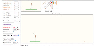
virtual trebuchet samples

Here are a few examples of what we tested


Meeting 1: Planning

May 5, 2013

We started planning the trebuchet by making a rough diagram and looking at videos to see how other people have made trebuchets. we also used a virtual simulator to test out some dimensions.